AVK FLANGED GATE VALVE, PN10/16
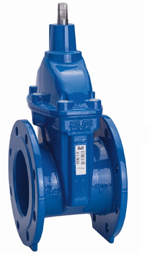
Gate valve for drinking water and other neutral fluids, including treated wastewater free of solids and fibrous impurities. Maximum operating temperature 70°C. Operating direction clockwise-to-open.
AVK gate valves are designed with built-in safety in every detail. The wedge is fully vulcanized with AVK's own drinking water approved EPDM rubber compound. It features an outstanding durability due to the ability of the rubber to regain its original shape, the double bonding vulcanization process and the sturdy wedge design. The triple safety stem sealing system, the high strength stem and the thorough corrosion protection safeguard the unmatched reliability.| Variant 06/30-042 | |
|---|---|
| Connection: | Flanged |
| Material: | Ductile iron |
| DN: | DN50 - DN400 |
| PN: | PN 16 |
| Closing direction: | Clockwise to Open |
Features
- Wedge nut in dezincification resistant brass, designed as a fixed, integral part of the wedge which prevents vibration and ensures durability
- Wedge and wedge nut fully encapsulated in drinking water approved EPDM
- A large conical stem hole going all the way through the wedge ensures circulation and prevents accumulation of stagnant water
- Stem in stainless steel with wedge stop and rolled threads for high strength
- Full circle thrust collar keeps the stem firmly lined up and ensures low operating torque
- Three independent stem seals: an NBR wiper ring protects against contamination from outside, four O-rings surround the radial bearing and innermost a lip seal acts as the main seal to the flow
- Bonnet gasket with a circular cross section fixed in a recess to avoid blow-out
- Bonnet bolts in A2-70, counterbored, sealed with hot melt glue and encircled by the bonnet gasket
- Corrosion protected with 250 µm fusion bonded epoxy to SANS 664, blue RAL 5017
Downloads
Appendix
Animation
| AVK_Gate valves_animation_2022.mp4 |
Outline drawings DWG
Outline drawings DXF
Outline drawings IGS
Outline drawings STEP
Reference nos. and dimensions:
Scroll for more info
| AVK ref. no. | DN mm |
Flange drilling |
H mm |
H1 mm |
L mm |
W mm |
F mm |
Theoretical weight/kg |
|---|---|---|---|---|---|---|---|---|
| 06-050-30-1143399 | 50 | PN16 | 208 | 150 | 165 | 14 | 9.0 | |
| 06-065-30-1143399 | 65 | PN16 | 244 | 170 | 185 | 17 | 11 | |
| 06-080-30-1143399 | 80 | PN16 | 282 | 180 | 200 | 17 | 14 | |
| 06-100-30-1143399 | 100 | PN16 | 305 | 190 | 220 | 19 | 17 | |
| 06-150-30-1143399 | 150 | PN16 | 400 | 210 | 285 | 19 | 31 | |
| 06-200-30-1143399 | 200 | PN16 | 400 | 210 | 285 | 19 | 48 | |
| 06-250-30-1143399 | 250 | PN16 | 625 | 250 | 400 | 27 | 78 | |
| 06-300-30-1143387 | 300 | PN16 | 740 | 270 | 455 | 27 | 111 | |
| 06-350-30-11433 | 350 | PN16 | 924 | 290 | 564 | 32 | 220 | |
| 06-400-30-11433 | 400 | PN16 | 951 | 310 | 580 | 32 | 240 |
Enquiry
Scroll for more info
Components
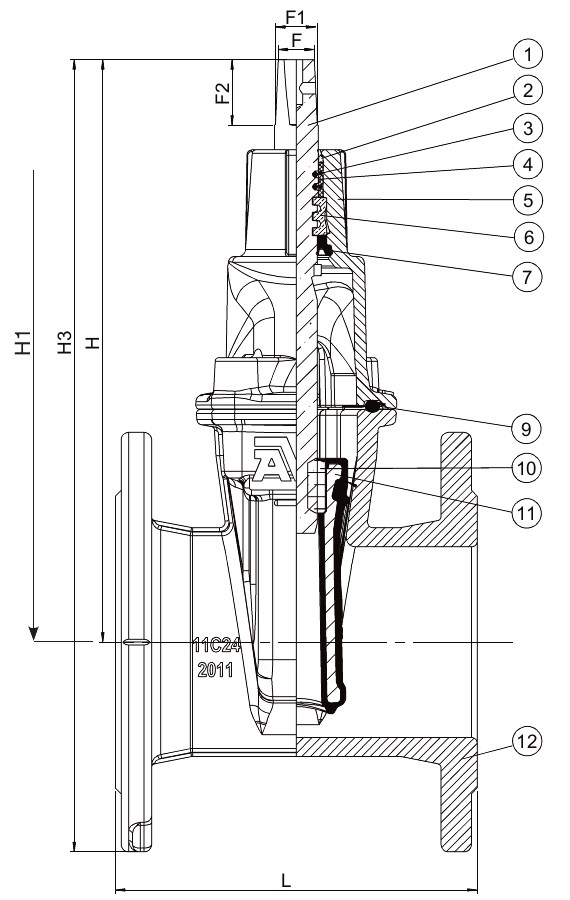
| 1. | Stop ring | Stainless steel 1.4021 |
| 2. | Stem | Stainless steel 1.4021 |
| 3. | Bonnet | Ductile iron GJS-500-7 |
| 4. | Bonnet gasket | EPDM rubber |
| 5. | Wedge nut | Brass DZR CW626N |
| 6. | Wedge rubber | EPDM rubber |
| 7. | Body | Ductile iron GJS-500-7 |
| 8. | Wiper ring | NBR rubber |
| 9. | O-ring | NBR rubber |
| 10. | O-ring | NBR rubber |
| 11. | Radial bearing | PA 6.6 |
| 12. | Thrust collar | Brass DZR CW602N |
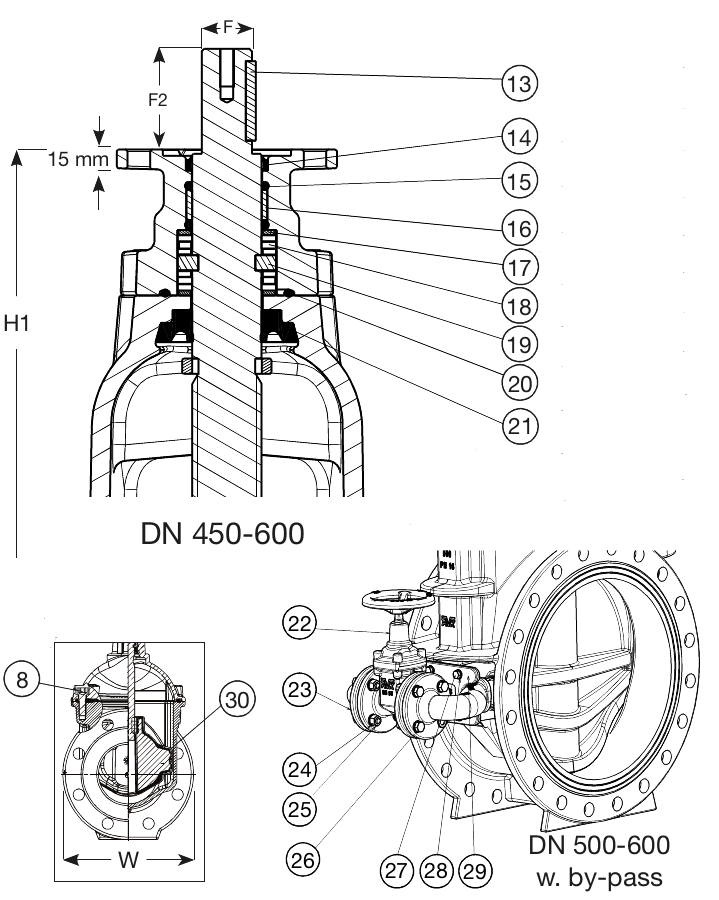
| 13. | Seal | Hot melt glue |
| 14. | Stem seal | EPDM rubber |
| 15. | Bonnet bolt | Stainless steel A2-70 |
| 16. | Wedge core | Ductile iron GJS-500-7 |
| 17. | Wedge shoe | PA 6.6 |
Test/Approvals
- Hydraulic test according to EN 1074-1 and -2 / EN 12266 |
- Seat: 1.1 x PN (in bar), Body: 1.5 x PN (in bar). Operation torque test
Standards
- EN 1074 part 1 & 2, EN 1171
- Face-to-face dimension according to EN 558, Series 14
- Flange drilling to EN1092, PN10/16